-
+86-19957487689
-
Комната 5-5, № 39, переулок 158, южный участок Западной кольцевой дороги, район Хайшу, город Нинбо, провинция Чжэцзян
- p.min2@demy-bearing.com


ООО Нинбо Дэмай Подшипники


How Do Track Roller Bearings Work in Industrial Automation Equipment?
2026-10-14
- Cam follower bearings use a thick outer ring to run directly on a track, cam, or guide surface.
- The outer ring, rolling elements, stud, lubrication system, and seals must be selected as one operating system.
- Load, speed, shock, contamination, misalignment, and track quality determine service life more than bearing size alone.
- Installation errors, inadequate lubrication, contamination, and poor track alignment are common causes of premature failure.
- OEM buyers should evaluate batch consistency, inspection capability, replacement availability, and technical support alongside price.
Track roller bearings for industrial automation equipment provide compact, repeatable linear or oscillating motion by rolling along a mating track instead of sliding over it. The SKF bearing selection principles explain why load direction, speed, temperature, lubrication, and operating conditions must be considered together, while ISO 281 defines a standardized approach for calculating bearing rating life. This article shows how cam follower bearings work, how to size them, and how to prevent common automation failures.
What Are Track Roller Bearings?
Track roller bearings are rolling bearings designed to run on a track, cam, guideway, or profiled surface. Unlike a conventional bearing that normally supports a rotating shaft inside a housing, a track roller typically has an outer ring intended to contact an external running surface. The inner assembly may use a stud, eccentric stud, yoke, or other mounting arrangement.
The outer ring is the working interface between the bearing and the track. It is usually thicker than the ring of a standard radial bearing because it must resist concentrated contact stress, local deformation, and repeated rolling impact. Depending on the design, the outer ring may be cylindrical, crowned, flanged, or profiled.
Cam follower bearings are a common form of track roller bearing used in indexing mechanisms, packaging equipment, robotic transfer units, linear guides, material handling systems, and automated assembly machines. A stud-mounted cam follower can be bolted directly to a lever or moving plate, reducing the number of separate housing components.
How Cam Follower Bearings Work
A cam follower bearing works by allowing its outer ring to roll along a stationary or moving track while the stud or inner assembly remains attached to the mechanism. As the cam profile changes, the bearing follows the path and transmits motion to the connected member.
Rolling contact reduces sliding friction, but it does not eliminate contact stress. The load passes through the outer ring, rolling elements, and inner ring or stud. If the track is too soft, rough, misaligned, or contaminated, the bearing can experience brinelling, smearing, pitting, spalling, or rapid wear.
The rolling elements distribute the load across a limited contact zone. Needle rollers are useful where a compact radial section is required, while cylindrical rollers can provide strong radial support in designs with more available space. Some track rollers use full-complement rolling elements to increase load capacity, although the designer must also consider friction, speed, lubrication, and heat generation.
Guidance geometry determines how the bearing stays on the track. A crowned outer ring can tolerate limited angular misalignment by reducing edge loading. Flanges or side rollers can control lateral movement, but they may introduce additional axial forces and friction. A flanged design is therefore not automatically better for every automation application.
Track Roller Bearings Versus Standard Automation Roller Bearings
Track rollers are optimized for external running surfaces, whereas standard roller bearings are normally installed in a housing and operate around a shaft. The distinction affects mounting, load distribution, lubrication, and maintenance.
| Design factor | Track roller bearing | Standard roller bearing | Typical evaluation count |
|---|---|---|---|
| Primary contact interface | Outer ring to track | Inner ring to shaft | 1 interface |
| Main motion type | Rolling along a profile | Rotating inside a housing | 1 motion system |
| Common mounting method | Stud, eccentric stud, or yoke | Shaft and housing fit | 2 primary fits |
| Track condition requirement | High importance | Usually handled by shaft and housing design | 1 external running surface |
| Load assessment | Radial, axial, shock, and edge loading | Radial, axial, or combined loading | 3 major load categories |
The numerical counts in this comparison describe design elements rather than performance ratings. Bearing manufacturers use detailed load, speed, and life calculations for a particular application; they should not be interpreted as universal capacity values. The Timken bearing damage analysis guide is useful when comparing visible damage with operating conditions.
Where Automation Roller Bearings Are Used
Automation roller bearings are most valuable when a machine must repeat a controlled path under limited space and frequent cycling. Consider a packaging machine in which a cam-driven arm opens, closes, and returns thousands of times during a production shift. A stud-mounted follower can transmit the cam motion without requiring a separate bearing housing at the moving joint.
Typical applications include:
- Indexing tables and cam-driven transfer mechanisms.
- Robotic grippers, pick-and-place slides, and end-of-arm tooling.
- Conveyor guide systems, chain guides, and material handling equipment.
- Packaging, labeling, filling, and inspection machinery.
- Automated doors, linear actuators, and profile rail mechanisms.
Application conditions matter more than the machine label. A clean inspection station may prioritize low noise and smooth motion, while a forming or stamping line may require stronger resistance to shock and contamination. A bearing that works well in one section of a machine may be unsuitable in another section with a different duty cycle or track surface.
How to Select Track Roller Bearings for Industrial Automation Equipment
The correct selection begins with the load path, not with the bearing catalog number. Identify where the force enters the outer ring, how the bearing is mounted, and whether the load changes direction during a cycle.
| Selection question | Why it matters | Evidence to collect | Priority level |
|---|---|---|---|
| Is the load radial, axial, or combined? | Determines internal stress and flange requirements | Force diagram and cycle description | 1 |
| Is the motion continuous, oscillating, or indexing? | Influences lubrication and heat generation | Speed profile and dwell time | 2 |
| Are shock loads present? | Raises risk of permanent deformation | Start-stop events and impact history | 3 |
| Is the track clean and hardened? | Controls external contact damage | Track material, hardness, roughness, and debris exposure | 4 |
| Can the assembly tolerate misalignment? | Reduces edge loading and uneven wear | Mounting tolerance and deflection review | 5 |
| Is maintenance access limited? | Determines seal and relubrication strategy | Service interval and access drawing | 6 |
Load and life calculation
Equivalent dynamic load should be calculated from the actual radial and axial components rather than estimated from the machine name. For applications with impact, acceleration, or changing force direction, use an appropriate service factor and validate the result with duty-cycle analysis.
Rating life is a calculation method, not a guarantee of field life. ISO 281 provides the recognized framework for basic dynamic load ratings and rating life, but actual service life can be reduced by contamination, poor lubrication, mounting damage, track defects, or excessive misalignment. For that reason, the life calculation should be paired with a track inspection and maintenance plan.
Speed and motion profile
Peak speed alone is insufficient for selecting automation roller bearings. A short high-speed movement followed by a long dwell produces a different thermal condition from continuous rotation at the same peak speed. Oscillation can also prevent the lubricant from redistributing evenly across the contact zone.
Record acceleration, deceleration, cycle frequency, reversal frequency, and dwell time. Where the bearing repeatedly reverses over a short path, inspect for false brinelling and fretting rather than evaluating the application only as a conventional rotating bearing.
Track and mounting design
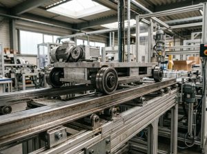
The mating track is part of the bearing system. A smooth, properly aligned, adequately supported track reduces local stress and helps the outer ring carry the intended load. A thin plate or unsupported guide can deflect under load, creating edge contact even when the bearing itself is correctly specified.
Stud tightening is equally important. Excessive tightening can distort the mounting area or interfere with designed clearance, while insufficient tightening can allow movement between the stud and machine member. Use the manufacturer installation instructions for torque, fit, locking method, and any required eccentric adjustment.
Common Failure Modes in Cam Follower Bearings
Most premature failures result from a mismatch between the bearing, track, lubricant, and installation method rather than from normal rolling fatigue alone.
- Lubrication starvation: Insufficient or unsuitable grease increases friction, temperature, and surface distress. Check grease compatibility, replenishment access, and the effect of water or cleaning chemicals.
- Contamination: Dust, metal particles, moisture, and process residue can indent raceways and accelerate fatigue. Seals help, but they cannot compensate for a contaminated track.
- Edge loading: Misalignment or shaft deflection concentrates force at one side of the outer ring. Crowning, improved mounting stiffness, or corrected geometry may be required.
- Track damage: Dents, weld spatter, interrupted surfaces, and inadequate hardness can create repeated impact points.
- Overload or shock: Static deformation may occur during jams, emergency stops, or accidental impacts even when the normal running load appears acceptable.
Failure analysis should compare the damaged zone with the load direction and motion path. A single repeated mark often points to a track defect or debris event, while uniform raceway fatigue may indicate long-term load, lubrication, or life-limit issues.
Procurement and Quality Checks for OEM Buyers
For OEM production, batch consistency is often more important than the best result from one sample. Confirm dimensional inspection, radial clearance control, noise and vibration evaluation, grease management, seal consistency, and traceability of production lots.
Ask suppliers to clarify the reference conditions behind capacity and life values. Confirm whether the stated values apply to the complete cam follower assembly, the bearing insert only, or a laboratory calculation. Also review replacement availability, packaging protection, technical response time, and the supplier’s ability to support engineering changes.
A practical validation plan should include incoming dimensional checks, installation trials, loaded cycling, temperature monitoring, noise review, and post-test inspection. The number of test cycles should be defined by the application risk and duty profile rather than copied from an unrelated machine.
FAQ
What is the difference between a track roller and a cam follower?
A cam follower is a track roller configured for mounting to a machine member, commonly through a stud. Track roller is the broader functional description for a bearing whose outer ring runs on an external track or profile.
Can a cam follower carry axial load?
Some designs can accommodate limited axial or side loads, but the allowable level depends on flange geometry, lubrication, speed, alignment, and the direction of contact. Do not assume that a radial cam follower is suitable for continuous side loading.
Why does the outer ring need to be thick?
The outer ring contacts the external track over a concentrated area and must resist rolling contact stress and local deformation. A thicker ring also improves resistance to dents caused by shock or track irregularities.
Should the track be hardened?
A hardened or otherwise suitable track can reduce indentation and wear, but the required material and surface condition depend on load, speed, contact geometry, and contamination. The track should be designed together with the bearing.
How does misalignment affect a track roller bearing?
Misalignment can shift the load toward one edge of the outer ring, increasing contact stress and wear. A crowned outer ring may tolerate limited angular error, but it cannot correct poor structural stiffness or a badly positioned track.
What lubricant is suitable for automation roller bearings?
Use the lubricant specified for the bearing and operating environment. Viscosity, base oil, thickener, temperature, water resistance, speed, and compatibility with existing grease all matter. Mixing greases without confirmation can reduce lubrication performance.
How can premature failure be prevented?
Control the track surface, mounting fit, tightening method, lubrication, sealing, alignment, and contamination. Record operating temperature and noise during commissioning, then use inspection findings to establish a condition-based maintenance schedule.
About the Supplier
Demy Bearings supports industrial customers with rolling bearing products for automation, motors, transmission systems, and other mechanical applications. Its product approach combines specification review, application-oriented selection, production consistency, inspection control, and OEM support. Buyers can review available bearing solutions through the bearing product website and contact the supplier directly to discuss drawings, operating conditions, replacement needs, and quotation requirements.
For an application-specific recommendation, provide the load direction, motion profile, track details, temperature, contamination level, mounting arrangement, and maintenance conditions with your inquiry.
Additional technical reference: ISO 281 bearing rating life standard.